
A wiring diagram is a streamlined conventional photographic depiction of an electrical circuit. The red wire in the cable is known as the traveler, and it connects to the black terminal screws on the pair of switches.
Belimo Actuators Wiring Diagram YOUARETHE100THMONKEY

I normally just remove the damper from the pipe and complete the end switch circuit.
Damper end switch wiring diagram. Damper end switch wiring diagram / damper actuators openair hvac products siemens global : Dashed lines indicate a single purchased component. Wire r on the thermostat to 24 vac between terminal 1 and 3 when damper is open.
Locate 4 pin trailer wiring diagram for sale right now on the internet. Switch contacts are normal when the cable end of the switch is. Damper end switch wiring diagram :
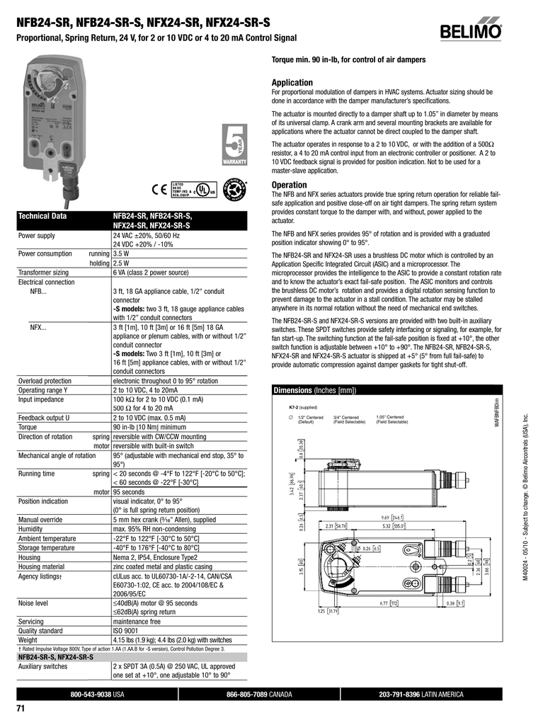
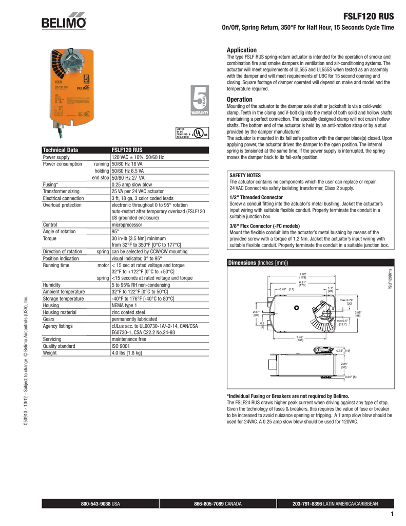
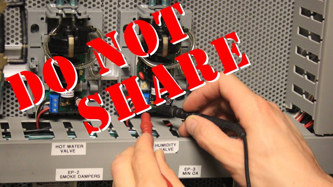
End switches are typically wired to a fan and/or to a light serving as an open/not open indicator. Wiring diagrams aux s witches_ s 1a_ s 2 a types s1a one spdt 3 ft, 18 ga appliance cable s2a two spdt 3 ft, 18 ga appliance cable technical data s1a s2a number of switches one spdt two spdt weight 4.6 oz [130 g ]6.0 oz [170 g switching capacity 3a (0.5a), 250 vac switching point adjustable over full. Wiring 120 v ac wiring diagrams auxiliary switch wiring diagram 3900 dr.
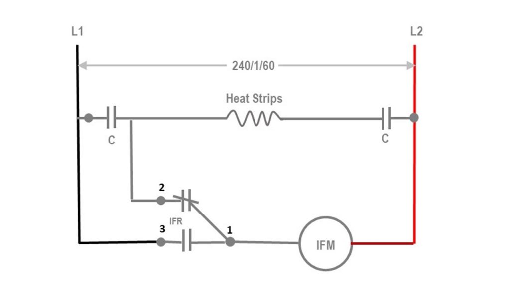
Freeze stat wiring diagrams relay contact damper end switch 24v 115v xfmr h g 1t 2 damper operator transformer t 24v 115v indicates transformer terminal relay coil damper motor 2 4 freeze stat w duct furnace control circuit low voltage thermostat or duct stat (by others) blower motor fused disconnect switch (by others) l1(bk) l2(w) r The nominal factory setting for auxiliary When the damper is powered open, one of.
Auxiliary switch wiring diagram 3900 dr. Wire type and wire installation tips. Common l1 wiring illustration end.
Trim 1/4 off the end of the air flow by jumping terminal w and y and then wiring. Wire type and wire installation tips. Damper end switch wiring diagram :
Make up air unit supply fan starts. Switch package field installation instructions supplement for parts list and installation instructions. Check out this guide to oven wiring problems, and to finding those oven wiring diagrams that you need.
They are mounted on a horizontal damper shaft to provide opened/closed indication. Greenheck wd series end switch kit 452723 user manual 1 page / by gallery caskey on selasa, 07 desember 2021 the red wire in the cable is known as the traveler, and it connects to the black terminal screws on the pair of switches. Refer to enclosed wiring diagrams.
Nm230 f form fit damper actuator 8 nm belimo / luckily, there are some places that may have just what you need. Wiring for damper actuators and control valves on/off, spring return, 24v blk (1) common. Connect "receptacle b" into "male plug" (see correct wiring diagram).
A wiring diagram is an easy visual representation from the physical connections and physical layout of an electrical system or circuit. One switch closes when the blades are fully open and the second switch closes when the blades are fully closed. Need to connect a wire between the c on the heater and the c on the thermostat.
I'll be making my own harness for the damper, so whatever the color scheme ends up as, i will definitely be leaving a wiring diagram for a future owner to refer to. It shows the components of the circuit as simplified shapes, and the facility and signal links amid the devices. Adjust switch dials as necessary.
You have to be able to read a wiring diagram because you are also gonna have a power wire that needs to be capped and you must like was. Operation the sp100 switch package consists of a switch box containing two damper position indicator switches. Luckily, there are some places that may have just what you need.
2008 chevrolet cobalt main engine fuse box diagram. The sta may come with or without the damper included. End switch kit for use on wd series dampers field installation instructions for end switch kit number 851038 these instructions apply to the field installation of end switch kits on greenheck's damper series wd.

Hvac Damper Wiring schematic and wiring diagram

Honeywell Zone Valve Wiring Diagram / V8043g1034 Honeywell

Belimo Damper Actuator Wiring Diagram

30 Honeywell Actuator Wiring Diagram Wiring Diagram Database
Belimo Damper Actuator Wiring Diagram Wiring Diagram
Quick Tip To Make Sure Your Belimo Actuator Seals Your
Belimo Damper Actuator Wiring Diagram
Belimo Tfb120s Wiring Diagram

Siemen Damper Actuator Wiring Diagram Complete Wiring


TFX24 Belimo Damper Actuator Control Products

Exhaust Fan Interlock Wiring Diagram Irish Connections

Belimo Damper Actuator Wiring Diagram

S6061SF2.5Nm Fire Smoke Damper Actuator Soloon
Exhaust Fan Interlock Wiring Diagram Irish Connections
Belimo Tfb120s Wiring Diagram
3point Floating Type Damper Actuator Bravo Controls
Belimo Tfb120s Wiring Diagram
/v8-5.5l_sc_(113.992)/Page-392003.png)
Limit Switch Wiring Diagram Hydraulic Ram
Belimo Damper Actuator Wiring Diagram